Without the parenthesis in the denominator the numerator is only divided by W and not W t26. Max 1 ξ V L.
2
Max 1 xi cdot V_ L.
. For producing a safe reliable design This is the most widely used lifting lug design standard. The equation seems appropriate. Therefore the requirement that special custom-design grabs hooks clamps or other lifting accessories be proof-tested prior to use is mandatory and failure to comply is a violation of OSHA requirements.
By varying the lengths of chokers a fixed-tilt lifting beam can be made as depicted in Fig. 1 5 min 1 xi. 3C the sling lengths can be calculated using the following formulae.
The ring has the shape of. CBS12 Structural OP 2 Dec 09 0004. Formwork adhesion Ha is calculated through the following equation.
ASME BTH-1 Design of Below-The-Hook Lifting Devices governs the design of lifting lugs for industries. Q 2 kNm² for varnished timber mould. My concern is the coding in the excell spreadsheet in which leaving out the parenthesis makes a significant difference.
We have a slab design 24m x 19m and 200mm thick with a 600mm square opening and cover in the middle. Dynamic factor. The author may have multiplied t instead of squared t as well.
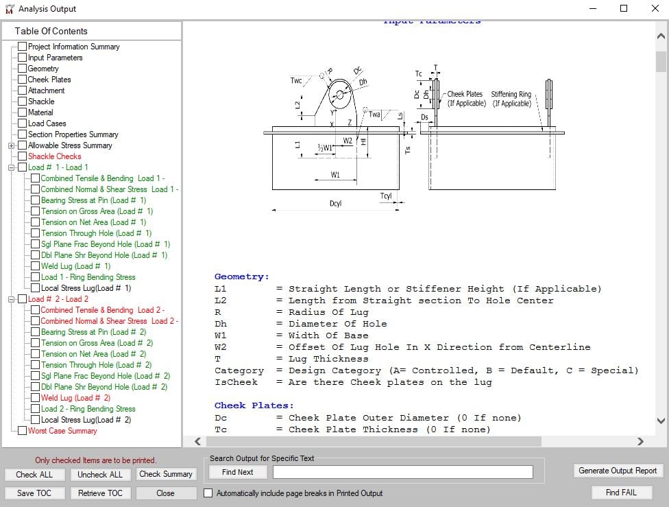
Useful graphical views of the lug and welding are foreseen to better define the geometry and the dimensioning parameters. Heres how you would calculate the load weight of an irregular shaped object made out of concrete. A lifting hook is a device for grabbing and lifting loads by means of a device such as a hoist or crane.
Metric SI or English UK Units System can be selected for the calculation. Dynamic Impact Factor Another important consideration is estimating the effect of dynamic impact on the lifting system. Area of contact between the mould and the concrete unit when starting to lift.
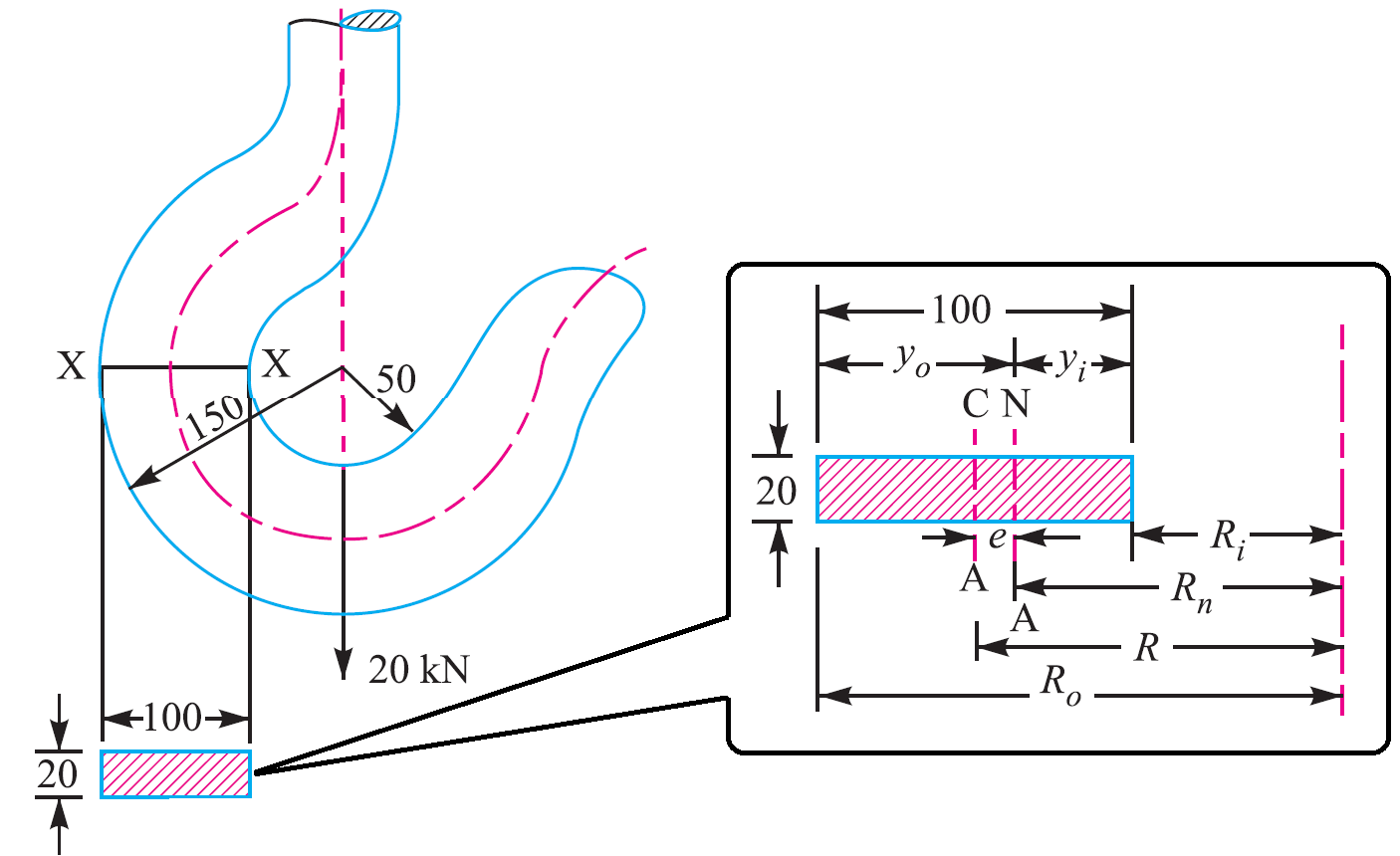
Area of this rectangular section X-X A Breadth b x Height h 20100 2000 mm². Q 1 kNm² for oiled steel mould. Min 1 ξ.
Tension on Sling T 1 2 V1 2 H1 2 12 Tension on Sling T 1 2 W legs sin a 1 2 Tension on Sling T. ASME BTH-1 specifies design calculations for different types of loading of a lifting device including tension compression flexure shear and combined loading of beams. As discussed in Reference 1 using a factor of 18 on AISC allowables results in a factor of safety of 5 for A36 steel.
Depending on the style of lifting device only certain structural. INTRODUCTION Crane hooks are highly liable. Bending stress in curved Beams This Crane hook is considered as the initially curved beam.
First separate the object into rectangles and then calculate the weight of each section individually and then combine them as shown below. The C-hook is designed and dimensioned for lifting and transporting the cut r ings with the maximum weight of 6500 kg Fig. 115 min1ξmax1ξV L.
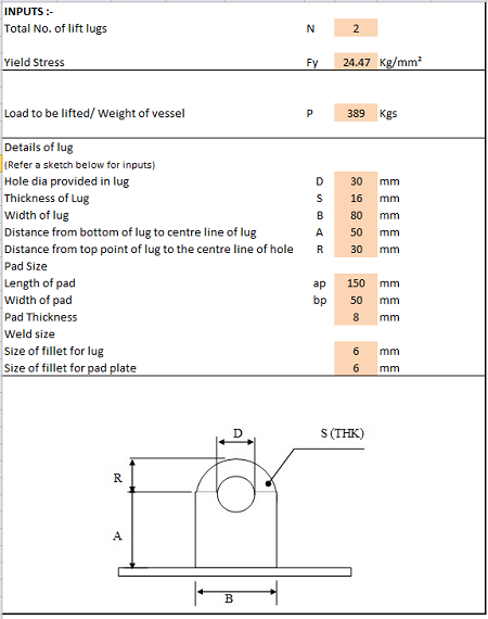
SHEAR ALLOWABLE Fv 04Fy TENSION ALLOWABLE Ft 06Fy COMBINED STRESS ALLOW Fa 066Fy BEARING STRESS ALLOW 09FY COMBINED STRESS ALLOW Fa 066Fy AREA Abt SECTION Sxtb26 Sybt26 SHEAR fv PhA SHEAR RESULTANT fvr fv2PER100fv205 IN PLANE BENDING STRESS PhhSx. Lprecast L al ar 600m 005m 005m 610m The lifting hooks will be positioned at a distance from the edge of the precast part of eam equal b to 20 of the length of the precast beam. Lifting hook design calculation Written By alfonzostraney88785 Saturday March 26.
Forged Steel Wrought Iron. Lifting hook material Prestressing strands When prestressing strands are used Ultimate tensile stress Fpu 1860 Nmm2 Diameter of strand Dia 953 mm Area of prestressing strand As 5484 mm2 Yield strength of strand Fy n Fpu As 40801 kN DL 25050 kN b Anchorage length check. The dimensions determinethe following length of the precast beam.
2 2 2 sinq long sling length. Volume 1 24 cubic feet. Expressed in terms of variables noted in Fig.
Here is the situation. 2 a H Ha. Using the design calculation from the modeling the analysis of hook is done in FEA software This result lead us to the determination of stress in existing model.
In this particular example the hooks will be at 02610m122m. The quantity of effective lifting points may be less than the quantity of real lifting points if the system is not balanced. 115 with ξ 03 for fixed crane or on rails and ξ 06 for crane bridge.
The distance between neutral axis to the outside fibre Y o R o R n. 1 a H Ha. Help with lifting hooks for slab.
Section X-X breadth b 20 mm. By predicting the stress concentration area the hook working life increase and reduce the failure stress. Q 3 kNm² for rough timber mould.
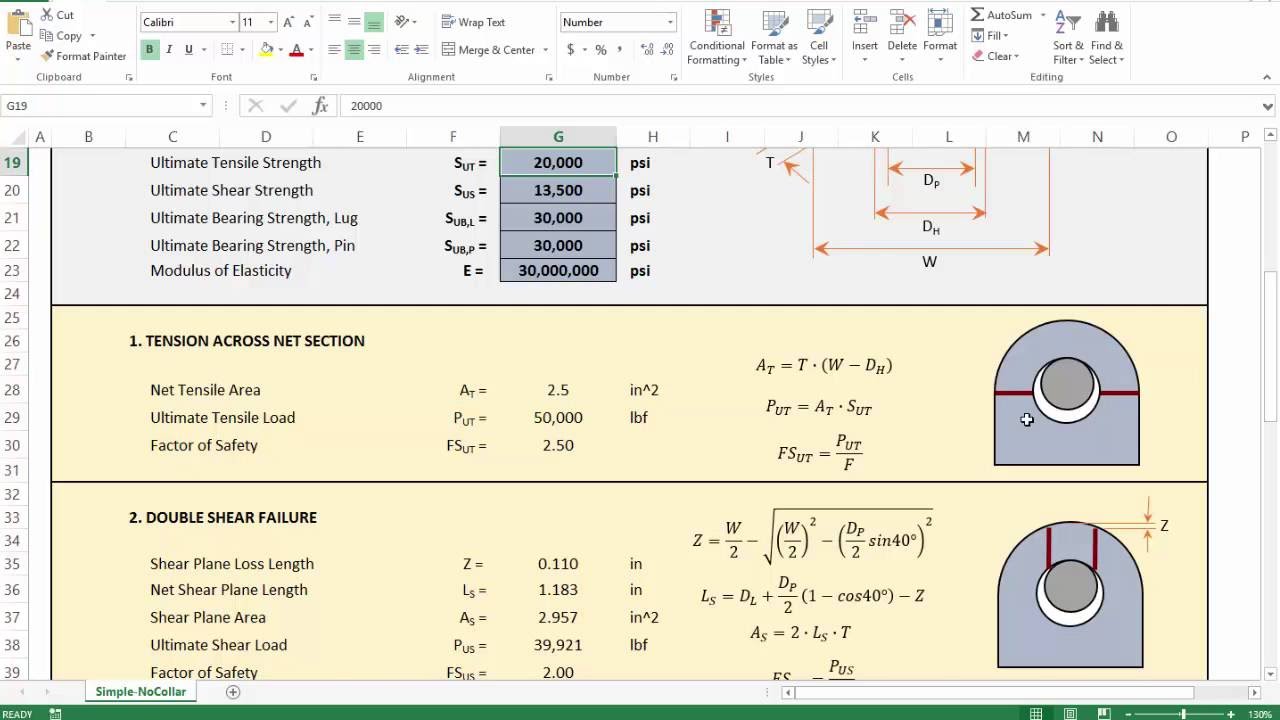
DesignEvalution of Overhead Lifting Lugs Page 7 1. Volume 1 Top 4 feet x 2 feet x 3 feet. Al 2009 this paper presents the different methods of stress calculation for lifting hooks based on different assumptions.
A lifting hook is usually equipped with a safety latch to prevent the disengagement of the. As a result different methods used to obtain the stress field on. This is in line with ASME B3020 which requires a design factor of 3 on yield strength and ANSI N146 which requires a design factor of 3 on yield strength and 5 on ultimate.
It is generally accepted that a sling angle α of 60 degrees β30 is the best compromise and therefore tends to be the default for most lifting designs. Another important consideration is the centre of gravity of the load to be lifted together with any accessories and or attachments used - slings grabs shackles hooks magnets vacuum pads etc. Ha q x A kN A.
Section X-X height h 100 mm. To attach the load locate the center of gravity position the crane hook directly above the center of gravity and then rig the load so that it will lift level and true. However As such standards do not clearly address the local stress calculation steps Finite Element Analysis is performed using various.
Calculations to be made will include the capacity both of the overall beam and of the loading of the individual lifting points. Calculation of Actual Working Loads and arrangement of. They applied curved beam theory Finite Element Method and photo elasticity experiments to obtain the stress field on the hook.
Ive never actually designed lifting hooks for a concrete slab before and would like to double check what Ive come up with and my reasoning. Welding verification between the lug and the bottom plate using the norm Eurocode 1993-1-82005 and NTC 2008.

Design Analysis And Weight Optimization Of Crane Hook A Review Semantic Scholar
Lifting Lug Design Mecalug Software Meca Enterprises Inc

Technical Drawing Of Hook Number 12 Download Scientific Diagram
Lifting Lug Design Spreadsheet Calculator
2
Crane Hook Design Problem Sample Extrudesign
4 Lifting Lug Analysis Simplified Youtube

Lifting Lug Design With Example What Is Piping
0 comments
Post a Comment